
First Author, Second Author, Third Author
First affiliation, Address, City and Postcode, Country
Second affiliation, Address, City and Postcode, Country
Abstract
This paper focuses on analyzing the power output of a Burritt turbine with special consideration to Ohms Law and the way great resistance affects the power output of the turbine. The paper will also put into consideration how circuits are connected and how they work in this particular turbine. Kirchhoff’s Voltage laws (KVL) in this case will be used to analyze the circuits while applying two types of circuits; parallel and series connections with the aid of diagrams. In this case the concept of Ohm’s law and Kirchhoff’s laws will be applied to give an in depth analysis and understanding of the power output in a turbine especially to a non-technical audience.
I. INTRODUCTION
Burritt rapid is a community hydro site waterway project, which is within the village of Burritt. This project is designed for the residents where they can see waterway, or see the rapid from their house. There are paths leading to the dam site from both sides of the river which is used for boating, fishing, hiking, contemplation, swimming and river flow up and downstream living conditions. Burritt hydropower project is initiated by Incorporated Community Association which is run by the board of local residents. The board is made up of 5 objectives related to the community vision to create a locally based energy which is community and environmentally friendly and which is a long term profit and returns to the community projects and well being.
The site where the dam is located has some historical meanings to the residents. This is associated with revisiting their roots of producing hydro energy from the water flowing through their community. The major idea here is to have a decision making and a partnership model for developing and operating this project. This is important to the residents who are prepared to play an active role along with experts and investors and government bodies. According to a survey of Burritt dam, the technical data that is available depicts that, the average annual flow of the turbine is 25m3/s, which is a range of approximately 10 – 70m/s2. The mean head drop is 2.3m which is on average is 1.36m – 2.43m. The estimated energy production of the turbine is 1900MWh or 222K w/month. The dam has an estimated construction cost of $5,300,000 before tax is levied. The estimated revenue that is targeted to generate per year is $258,000.
In order to make the residents of Burritt village (who are mostly non-technical) understand the concept of how power is generated by a turbine in a hydro power station, the concept of ohms law is applied. The circuit connection (both parallel and series) is better understood by use of Kirchhoff’s law. Since the residents are mostly non-tec hnical, use of models and diagrams will be used to make them better understand this concept.
II. QUESTION 1: OHMS LAW
Ohm’s law is used in electrical engineering to give us the relationship between current, voltage and resistance in any electrical component. The law states that that the change in electric potential (V) between two points on a conductor is equal to product of sum of resistance (R) of all the electrical appliances and current (I) between the two points. This law is best understood when expressed in equation form by using V, for electric potential, or, for resistance and I, for electric current [1]. The relationship between greater resistance and voltage in terms of power can be shown as follows. The basic formula involving power is: W = V x I or W = I2 x R or W = V2 / R
Equation 1: V= W/I2 R [6]
Where W is power, V is the potential difference between two points in the conductor, I is the current flowing through the resistor and R is the material tending to offer resistance to the flow of current which is measured in ohms [2]. This equation is in most cases used as a predictor of how potential difference, current and resistance relate to each other [2]. The relationship is also used to solve simple circuits [3]. For easier understanding, the law can be presented in figure form as shown below:
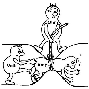
Figure 1: Representation of Ohms Law [4]
The law can also be represented in graphical form as ;
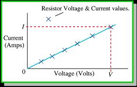
Figure 2: Graph of Ohms Law [4]
Circuit components in Ohms Law can be connected in parallel, series or a combination of the two. With series combination of circuit components, the;
• The drop in voltage is equal to the total voltage in the system.
• The same current is shared by all the components.
• Resistances cumulates to total resistance in the system.
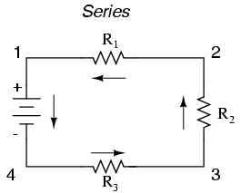
Figure 3: series combination of components [5]
In parallel combination of electrical components;
• Voltage is shared equally by all the components.
• Individual branch currents sum up to total current in the system.
• Individual resistances add up to the total resistance.
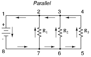
Figure 4: components in parallel [5]
It is worth noting that when the resistance is too high in circuit connections, the power output is lowered. This follows from Ohm’s law that the voltage drop across a conductor is directly proportional to current. This shows that:
V α I; hence V = KI, where K is regarded as the resistance of the components represented as R. The equation this reduces to V = IR and
Equation 2: I = V/R [6]
Equation (ii) clearly indicates that when the resistance is increased at constant voltage, then the power output will be lowered.
From the principle of conservation of energy, energy cannot be created nor destroyed but can be converted from one form to another. This is the case with power produced by the turbines. The amount of power produced may depend on the amount of resistance in the circuit. Resistance is known to increase in the circuit voltage and so increase in resistance in the circuit will make alterations in the pathway of the circuit. This alteration will consequently make voltage to change, current or both. Addition of more resisistance affects the voltage in the circuit and current in a different way depending on the way the resistance is added; series or parallel connections. When one or two resistances are added to the system in a series, the amount of total current will reduce and will also reduce the drop in voltage across each resistor. The system maintains the same total voltage. The sum of voltage drop in a series circuit equal to the voltage applied and so if resistance is added in parallel to the circuit with an already existing resistor in the circuit, then the total current in the system increases and the voltage across the added resistor remains the same for the existing resistor. This will also be equal to the voltage applied [6].
Generally, the voltage goes up for a fixed resistance and vice versa, while if the resistance goes up for fixed voltage, the current goes up and vice versa. It should be understood that resistance is the resistance to current flow and so if there is more of it then, less current will flow and vice versa. This follows from the relationships; V = IR, R = V/I, and I = V/R [1].
III. QUESTION 2: THE WORKING OF CIRCUITS IN A TURBINE
Electricity produced in hydroelectric plants uses the concepts of captured energy of falling water. Turbines are used to convert kinetic energy in dropping water to mechanical energy whereby a generator is consequently used to convert the mechanical energy into electrical energy [8]. When analyzing the circuit networks in turbines and other electrical circuits, Kirchhoff’s law is basically applied. Kirchhoff’s Voltage Law (KVL) basically states that the sum voltages across any closed loop are equal to zero [1] [9].
Equation 3: Ʃ V across branches = 0 [6]
Kirchhoff’s Voltage law is one of the fundamental laws applied in electronics [1]. The measured of power out is either positive when measured in the clockwise or anticlockwise direction [1]. What is assumed here is that the current creates a voltage across each resistor and fixes the position of the “+” and the “-“ signs such that the passive sign convention has to be obeyed. The sum of the voltages in the loop may be done in any other direction because it makes no difference provided that the signs in the resulting equation are changed [10].
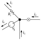
Figure 5: Current in a closed loop [11]
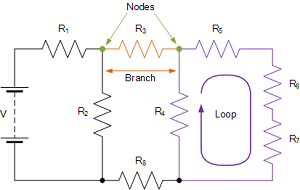
Figure 6: Closed loops and nodes [11]
In Kirchhoff’s Voltage Law, components may be connected in parallel or in series. Components are said to be in the series when connected end to end and in one line, in is one after the other. Under this connection there is only a single path for current flow. The current is assumed to be the same when components are in series connection. The concept of Ohm’s law may be applied under this case. When resistances appear in a series connection, the resultant resistance in the circuit is the sum of the resistances in the paths of the circuit [12] [13]; hence
Equation 4: RT = R1 + R2 +…….. + Rn [13]
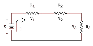
Figure 7: Resistance in series connection [11]
In a series connection, the total voltage across the circuit is equivalent to the algebraic sum of the voltages across each resistance in the circuit [13]; hence’
Equation 5: VT = V1 + V2 +…………. + Vn
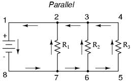
Figure 8: Resistances in parallel connection [11]
When resistances are connected in parallel, the voltage drop is the salve for all the resistances in the circuit. This means that;
Equation 6: V1 = V2 = V3 =…………….Vn [13]
And the total current is equal the algebraic sum of all the currents in the circuit; hence
Equation 7: IT = I1 + I2 +…….. + In [13]
From equation (vii);
I = V (V/R1 + V/R2) = V (1/R1 + 1/R2); hence I = V (1/RPARALLEL) which in general can be expressed as;
Equation 8: 1/RPARALLEL = 1/R1 + 1/R2 +………… + 1/R3 [13] [14]
Generally, in hydropower plants where turbines are used to generate electric power, the power produced can be relayed to appliances using either series combination of components, the parallel combination of components or a combination of two [15]. This will depend on where and how the power produced is being used in those particular appliances.
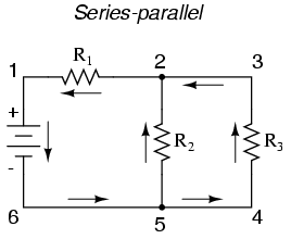
Figure 9: Series-Parallel combination of resistances [11]
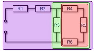
Figure 10: Model of a series-parallel connection [11]
IV. SUMMARY
In summary, Ohm’s law and Kirchirchhoff’s Voltage Law are fundamental laws in engineering and electronics. They provide both theory of how circuits can be arranged and the effective output when arranged in certain ways. The amount of power produced may depend on the amount of resistance in the circuit. This depends on the arrangement of resistance in the circuit; either series or parallel connection. When one or two resistances are added to the system in a series, the amount of total current will reduce and will also reduce the drop in voltage across each resistor. If resistance is added in parallel to the circuit with an already existing resistor in the circuit, then the total current in the system increases and the voltage across the added resistor remains the same for the existing resistor.
REFERENCES
[1] J. Irwin, R. Nelms, “Resistive Circuits,”in Basic Engineering Circuit Analysis, 10thed. C-K, 2011, ch. 2, sec. 2.2, pp. 26-39.
[2] Ohms law. [ Online]. Available:
http://www.physicsclassroom.com/class/circuits/Lesson-3/Ohm-s-Law
[3] R. Nave. Voltage Law. [Online]. Available: http://www.physics.uoguelph.ca/tutorials/ohm/Q.ohm.intro.html
[4] Ohms Law Teaching Aid. [Online]. Avaialble:
https://www.google.com/search?q=ohms+law&start=10&newwindow=1&client=firefox-a&sa=N&rls=org.mozilla:en-US:official&biw=1024&bih=567&tbm=isch&imgil=jMGJmX46ooHY4M%253A%253Bhttps%253A%252F%252Fencrypted-tbn1.gstatic.com%252Fimages%253Fq%253Dtbn%253AANd9GcQ0JNnNAYimQBDFIaV1U8qj_PONMh2Wzs_Lz2yNwd6dX2PlWmL1%253B300%253B191%253BguTg0EkvBscs3M%253Bhttp%25253A%25252F%25252Fphet.colorado.edu%25252Fen%25252Fsimulation%25252Fohms-law&source=iu&usg=__UOcqzB_Wk1dYcaAUVqBh233d1No%3D&ei=aLhvU9GSNKaa1AXa84HQBQ&ved=0CCsQ9QEwADgK#facrc=_&imgdii=_&imgrc=qZv4Zmx8UqhuKM%253A%3BdHtTNLt2cWjsUM%3Bhttp%253A%252F%252Fvoip.southcars.com%252Fmain%252Ffiles%252FGRAPHICS%252Fohms-law-1.gif%3Bhttp%253A%252F%252Fvoip.southcars.com%252Fmain%252Fnode%252F119%3B495%3B497
[5] J. Swanson, J. Yowell (2013.) The Power of Food.[Online]. Available: http://www.teachengineering.org/view_activity.php?url=collection/cmu_/activities/cmu_fruit/cmu_fruit_activity1.xml
[6] (2014.) Electrical Resistance. [Online]. Avaialble: http://www.thefreedictionary.com/electrical+resistance
[7] Y. To?ru, E. Meng. Practical Guide for Clinical Neurophysiologic Testing: Eeg. Philadelphia, PA: Lippincott Williams & Wilkins, 2010, ch. 3 pp 40 – 41
[8] W, Hermann-Josef, J. Mathur. Introduction to Hydro Energy Systems: Basics, Technology and Operation. Berlin: Springer, 2011, ch. 5 pp. 76 – 92
[9] L.D. Constantinovici, M. Govindsamy. Basic Circuit Analysis for Electrical Engineering. Kenwyn: Juta, 1999. Un. 5 pt 1 pp. 126.
[10] Kirchhoff’s Voltage Law. [Online]. Avaialble:
http://web.engr.oregonstate.edu/~traylor/ece112/lectures/kvl.pdf
[11] Kirchhoff’s Voltage Law. [Online]. Avaialble:
https://www.google.com/search?q=-%09Kirchhoff%27s+Voltage+Law+%28KVL%29+and+Circuit+Analysis&newwindow=1&client=firefox-a&hs=Gyx&rls=org.mozilla:en-US:official&source=lnms&tbm=isch&sa=X&ei=0-9vU-q4DsvO0AXG44HwBA&ved=0CAkQ_AUoAg&biw=1024&bih=567
[12] A. H. Robbins, W. Miller. Circuit Analysis: Practice and Theory. Cengage. 2012. Ch. 18 pp.619 – 620
[13 ] Kirchhoff’s Law. [Online]. Available:
http://physicsfiles.com/series_parallel_circuit_notes.PDF
[14] Kirchhoff’s Rules. [Online]. Avaialble:
http://www2.ignatius.edu/faculty/decarlo/kirchhoff.htm
[15] Combination circuits. [Online]. Avaialble:
http://www.physicsclassroom.com/class/circuits/Lesson-4/Combination-Circuits
|
Grammar
D
|
Formatting
C
|
Organization
D
|
Style
D
|
